


Custom High-Pressure Die Casting
Small and medium castings need a coordinated plan for the alloy, die, quantity and critical features. Our HPDC range is 88–650T, with casting, CNC finishing and inspection reviewed together for the part.













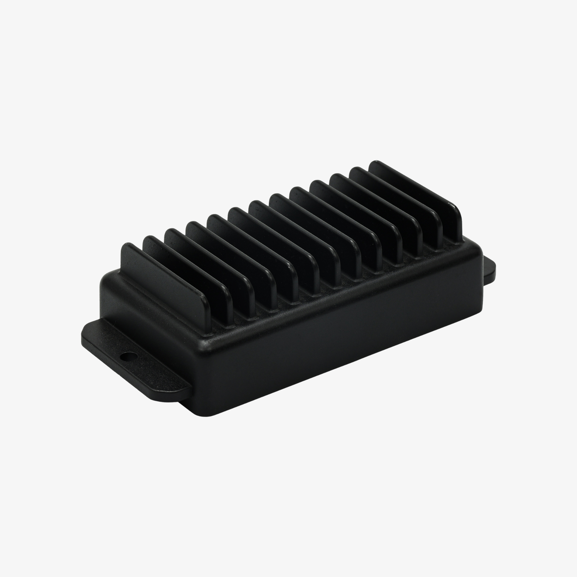

High-Pressure Die Casting and Secondary Operations
Alloy and projected area determine how the press range is assessed before the die and secondary operations are defined. The capability table separates as-cast dimensions from CNC-machined features; its best values are not guaranteed for every geometry.


Match the Alloy and Press
Part size, shot weight and projected area are reviewed before tool design. Maximum shot references are 4.0 kg for aluminum and 6.0 kg for zinc. The two 88T machines are for small zinc parts, so the aluminum range must not be applied to them.

Alloy and press
Shot and projected area
88 T small zinc only

Plan the Die and Ejection
Controlled wall transitions, alloy-appropriate draft, parting lines and ejector locations support the design review. Cosmetic surfaces and small holes need drawing callouts so release, filling and later drilling can be assessed together.
Draft and release
Parting and ejection
Cosmetic faces

Define CNC Finishing and Sealing
Datum faces, holes and threads may need machining after casting and must be identified. Leak-tight or pressure-tight requirements belong in the RFQ, allowing tooling, impregnation and the test method to be agreed for the application.
Machined datums
Leak criteria
Inspection review
LEAD MFG Die Casting Capabilities
The 88–650 T in-house range covers six HPDC presses; the two 88 T presses are for small zinc parts. Maximum dimensions depend on the alloy, projected area, die and filling. Casting tolerances and CNC-machined datums are separate. Scroll horizontally on narrower screens to read all conditions.
Parameter | Capability | Conditions |
|---|---|---|
Part size reference | ≤400 × 400 × 200 mm at 650T | Projected area reference approximately 1080 cm²; alloy, filling, cavity layout and pressure require review. |
Shot weight | Aluminum ≤4.0 kg; zinc ≤6.0 kg | Alloy-specific shot references; usable cavity and runner layout must be checked. |
Casting tolerance grade | Standard CT6–CT7; best CT5 | ISO 8062-3 reference; CT5 is for stable thin-wall conditions. |
As-cast linear dimensions | Standard ±0.10 mm / 100 mm; best ±0.05 mm / 100 mm | Best applies to stable thin-wall parts, not every geometry or alloy. |
CNC-machined datums | Standard ±0.010 mm; best ±0.005 mm | Machined faces only; best requires fine machining and CMM verification. |
Hole position | As-cast ±0.150 mm; machined ±0.020 mm | Best references: as-cast ±0.080 mm / machined ±0.010 mm; keep casting and machining scopes distinct. |
Wall thickness | Zinc 0.75 mm; aluminum 1.2 mm; magnesium 1.0 mm | Typical 1.5–4.0 mm; alloy, flow length and geometry govern filling. |
Small cast features / holes | Feature 0.5 mm; cast hole Ø2.0 mm | Smaller holes require drilling rather than a smaller cast-hole promise. |
Draft | Aluminum 1–2°; zinc 0.5–1° | Final die surface, alloy and release direction govern the design. |
Surface roughness | As-cast Ra 1.6–6.3 µm; blasted Ra 3.2 µm | Ra 0.8 µm applies to CNC-machined faces, not the complete as-cast part. |
Die Casting Materials
Die steel and the finished casting alloy are separate material choices. The technical source lists H13 tooling and aluminum, zinc and magnesium grades; the quotation confirms the chosen grade, material condition and finishing requirements.
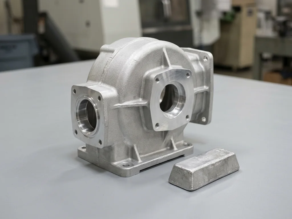
Aluminum Die Casting

Zinc Die Casting

Magnesium Die Casting
Tooling Material: H13
H13 is the listed die steel reference. Tool hardness is 46–48 HRC; the grade and heat treatment must suit the alloy and agreed tool design. Die material and heat treatment form part of the tooling agreement. H13 has a source reference of 46–48 HRC; an alternate trade name is not an approved substitution. The source lists 50,000–100,000 shots for aluminum and over 500,000 for zinc with H13 tooling. These are planning references, not an order-specific life guarantee; agree maintenance and life requirements with the tool quotation.
DM6, HA6, HA4, 6063 and AM50A can be discussed as material requests. Confirm the designation, suitability for the casting process and availability for the specific project.
Die Casting Finishes & Secondary Operations
Alloy, appearance and service environment guide finish selection. As-cast surfaces need to be distinguished from blasted or CNC-machined faces, and leak-tight requirements identified before tool design. Availability and processing route depend on the part and quotation.
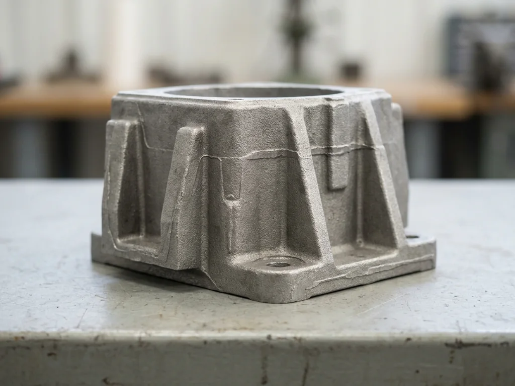
As Cast
As Cast
As-cast roughness is Ra 1.6–6.3 µm in the source. Define acceptable parting lines, ejector marks and cosmetic zones on the drawing.

Shot Blasting
Shot Blasting
The shot-blasted surface reference is Ra 3.2 µm. Agree the texture and cosmetic acceptance for the alloy and part.

Vibratory Deburring
Vibratory Deburring
Vibratory deburring is listed for post-cast processing. Identify edges and functional surfaces that need protection or separate acceptance criteria.

CNC Machining
CNC Machining
CNC finishing is used for critical datums, holes and mating faces. The surface reference is Ra 0.8 µm on machined faces; casting and machining tolerances remain separate.

Impregnation
Impregnation
Impregnation is listed for leak-tight parts. State the pressure or leak requirement and agree the test and acceptance criteria; sealing performance is not inferred from appearance.





Industry slide guide: 1: Automotive; 2: Consumer Electronics; 3: Lighting; 4: Medical Devices; 5: Automation; 6: Industrial Machinery.
Die Casting Component Requirements
The categories below help describe a part for review. Application examples are not evidence of completed customer projects, regulatory approval or guaranteed performance. Enclosure geometry, cleaning exposure, cosmetic surfaces and applicable compliance requirements define the project review. Motor housings and gearbox covers are source-listed candidates. Identify load cases, machined interfaces, temperature and leak requirements for the assembly. Brackets and housings need defined geometry, mating datums and loading requirements. Critical interfaces may need CNC finishing after casting. LED heatsink housings are a source-listed candidate. Specify thermal, mounting, coating and cosmetic requirements rather than assuming performance from the shape.
Die Casting for Automotive
For automotive die-cast parts, define the casting alloy, projected area, tool parting line and critical datums for any post-cast machining.
View MoreDie Casting for Consumer Electronics
Enclosure geometry, mounting features, cosmetic surfaces and operating environment establish the requirements for choosing an alloy and finish.
View MoreDie Casting for Lighting
For lighting housings, specify the casting alloy, surface appearance, mounting points and any faces that need secondary machining.
View MoreDie Casting for Medical Devices
A device enclosure may require a specified casting alloy, controlled cosmetic surfaces and inspection records. Review the applicable requirements for the intended device and project.
View MoreDie Casting for Automation
For die-cast automation parts, specify the alloy, wall geometry, draft and areas for subsequent machining. Review the tooling plan and critical dimensions with the drawing.
View MoreDie Casting for Industrial Machinery
Loading, mating datums, service temperature and sealing requirements guide alloy selection and secondary machining.
View More
Frequently asked questions
Tooling cost, alloy, porosity, inspection and CNC finishing define the initial discussion. A model and project requirements provide the basis for the detailed review. We can sign an NDA upon request before you share design files.
How much does a die casting project cost?

Cost depends on tooling, alloy and shot weight, cavity count, quantity and secondary operations. Machined datums and leak-tight requirements affect the work required. We can sign an NDA upon request before you share design files. A 3D model is required; a 2D drawing is recommended. The quotation defines review, tooling, sampling and production charges.
How does LEAD MFG minimize porosity in die cast parts?
Porosity and leak-tightness must be addressed during the part and tool review. Declare pressure or leak requirements up front so filling, venting, impregnation and the inspection method can be evaluated. A low-porosity or leak-tight result needs agreed acceptance criteria for the casting.
What should I consider when designing for die casting?
Uniform wall sections and reviewed transitions, fillets, parting lines and ejector locations guide the casting design. Draft references are 1–2° for aluminum and 0.5–1° for zinc. Cast holes must be Ø2.0 mm or larger; smaller holes require drilling. Cosmetic faces and machining stock need to be marked on the drawing.
How are cast and machined parts inspected?
The best ±0.005 mm CNC datum reference requires fine machining and CMM verification; it is neither an as-cast tolerance nor a value for every feature. The drawing needs the datum system, dimensions and inspection method. Dimensional, appearance, pressure and leak tests need to be identified in the RFQ. A sampling inspection report is free; full-inspection and FAI reports are paid services agreed in the quotation.
How are tooling and production schedules agreed?
Orders start at one piece, with typical batches of 10–1,000 parts; the tooling and manufacturing route must be agreed for the project. A prototype tool has a source reference of 12–18 days to the first trial; a production tool has a 3–4 week reference. Tool design, trial acceptance, the alloy, part quantity and production schedule must be agreed for the project. For 10–100 parts, the source production reference is 3–10 business days from quotation confirmation when an accepted tool, alloy and process are already available. Expediting is normally unavailable; urgent exceptions require confirmation. Manufacturing and transit are separate.