


Gravity Die Casting
Reusable dies, alloy condition, cores and secondary machining all shape a gravity-cast component. LEAD MFG reviews them together against the drawing, quantity and inspection needs.
Discuss Your Gravity Casting Project


Upload Your CAD Files for Fast DFM & Quote
.step.iges.stl.pdf.dwg
Gravity Casting: Process and Tooling
Gravity casting fills a reusable metal die under gravity. Alloy, die temperature, gates, feeders, cores and later machining need project-specific review; high-pressure and low-pressure die casting are distinct methods.


Reusable Metal Die
The die design must resolve the cavity, gates, feeders, parting line and machining stock for the drawing. Cores, vents and ejectors are arranged and confirmed before tool manufacture.

Parting and cavity
Gates and feeders
Tooling review

Gravity Filling and Solidification
Metal is poured into the reusable die under gravity. Die temperature, coating, venting, feeding and cooling affect filling, shrinkage and the part-removal plan.
Gravity pouring
Temperature and coating
Cores and cooling
Finishing and Machined Interfaces
Sealing faces, bores, threads and mounting datums may require CNC machining after casting. Machining stock and finished-feature tolerances must remain separate from as-cast reference values.
Trimming and machining
Mating datums
Acceptance criteria
Gravity Die Casting: Typical Engineering Reference
These figures are typical process design references from the supplied capability profiles. They are not verified LEAD MFG equipment ratings or a guarantee for every order; achievable values depend on material, geometry, size, tooling, processing method and agreed inspection scope. Scroll horizontally to read all conditions.
Parameter | Industry reference | Conditions |
|---|---|---|
Maximum Part Size | 800 × 600 × 300 mm | Conditional: 600 × 400 × 200 mm (high-accuracy zone). Limited by die opening and clamping |
Aluminium casting weight reference | 0.1–50 kg | 0.2–20 kg is the source economic band, not a minimum order or a tighter precision range. |
Minimum Wall Thickness | Al 2.5 mm | Conditional: 2.0 mm over small areas. Mg 2.0 mm; copper alloys 3.5 mm |
Machining Allowance | 1.5–3 mm | 1.0–1.5 mm is a small-part example; confirm machining stock for the alloy, geometry and proposed process. |
Minimum Cast Hole | φ4 mm (steel core) | Conditional: φ3 mm (small parts). Deep holes are better drilled |
Surface Roughness | Ra 6.3–12.5 μm | Conditional: Ra 3.2–6.3 μm (polished mould). Coating and mould temperature drive appearance |
Tooling Life | 50,000–80,000 shots | Conditional: 100,000–150,000 shots (hardened H13). Molten aluminium is thermally aggressive |
Linear ≤100 mm | ±0.4 mm | Conditional: ±0.3 mm. DCTG 7–9 / 6–7 |
Linear 100–300 mm | ±0.6 mm | Conditional: ±0.4 mm. Affected by thermal expansion of the mould |
Linear >300 mm | Drawing-specific tolerance | ±0.8 mm is a source example, not a uniform limit above 300 mm. Confirm the dimension, alloy, DCTG, die and inspection for the actual casting; ±0.6 mm is a conditional example. |
Wall thickness | ±5% | ±3% is a conditional reference; the achievable result depends on alloy, geometry, die and inspection. |
Machined face Ra | Ra 3.2 μm (milled) | Conditional: Ra 1.6 μm (ground). As-cast Ra 6.3–12.5 |
Airtightness | 0.3 MPa / 30 s, no leak | Conditional: 0.6 MPa / 60 s. Impregnation quoted separately |
As-cast grade and draft | DCTG 7–9; external draft ≥1.5° | DCTG 6–7 is a precision casting reference; machined features require separately specified tolerances. Internal DFM draft ≥2.5°; deep pockets 3–5°. |
Materials for Gravity Casting
Grade and condition references give a starting point for the casting discussion. The quotation must confirm material availability, section thickness, sampling location and any heat treatment. Alloy names describe the finished casting; die and core materials are separate. Availability and supplier capability must be confirmed.
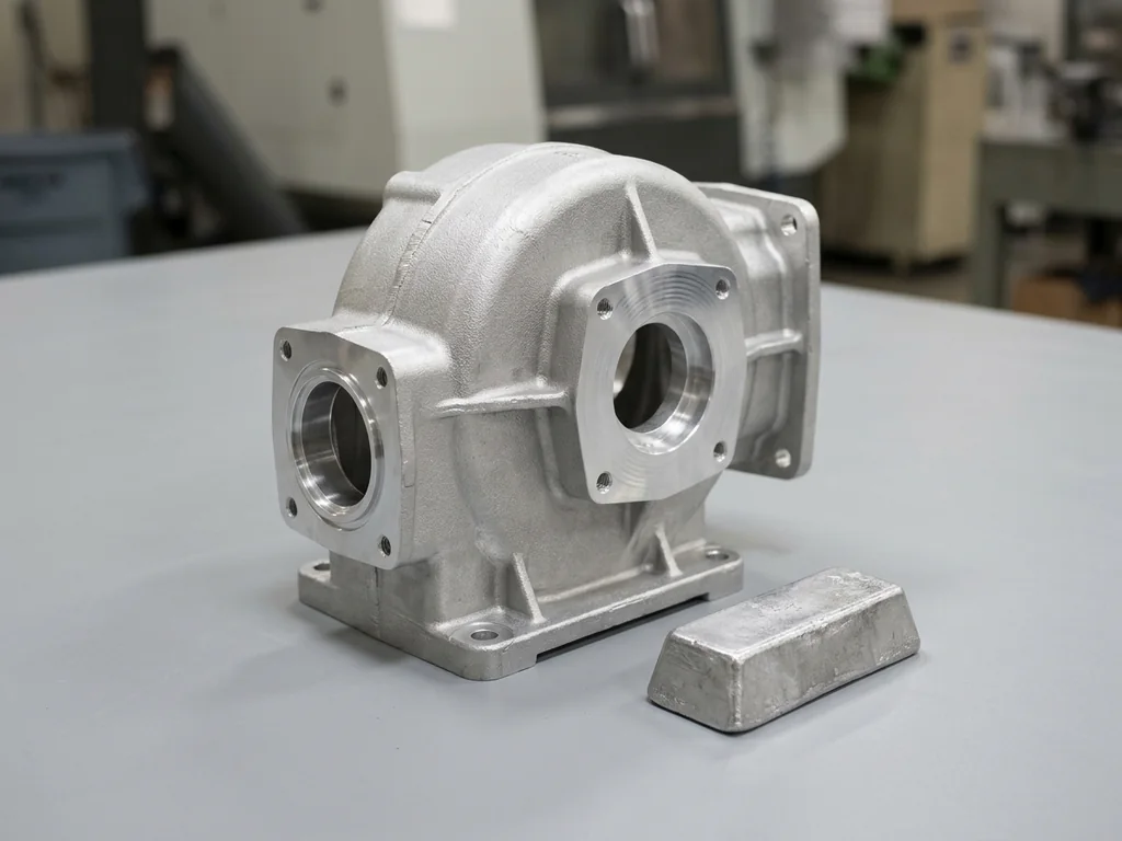
Aluminum Alloys
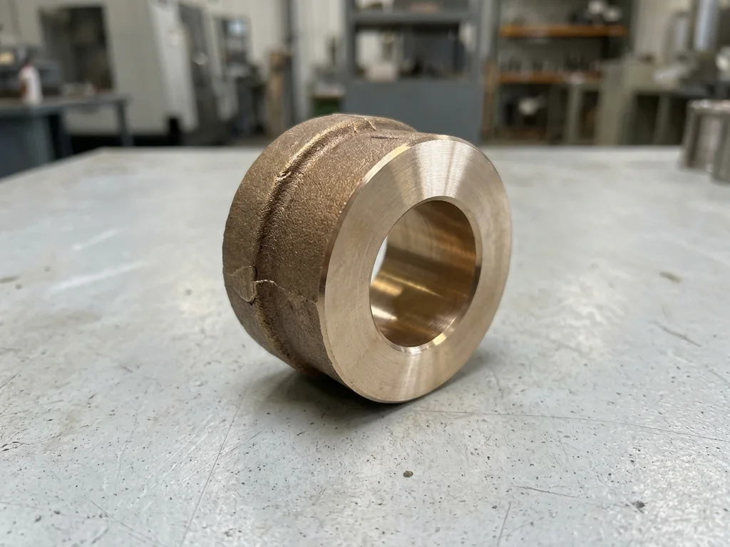
Copper Alloys

Zinc Alloys

Magnesium Alloys
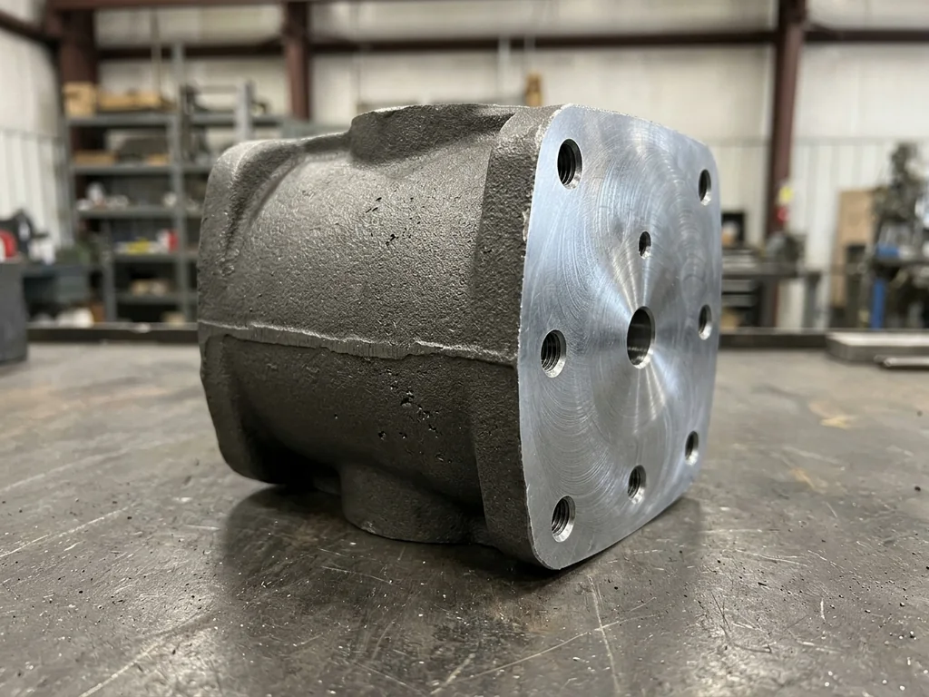
Iron-Based Casting Request
Secondary Operations for Gravity Die Casting
Secondary operations depend on the alloy, machined interfaces and service environment. Each area needs a specified surface condition and acceptance reference; the same finish is not assumed for every casting.
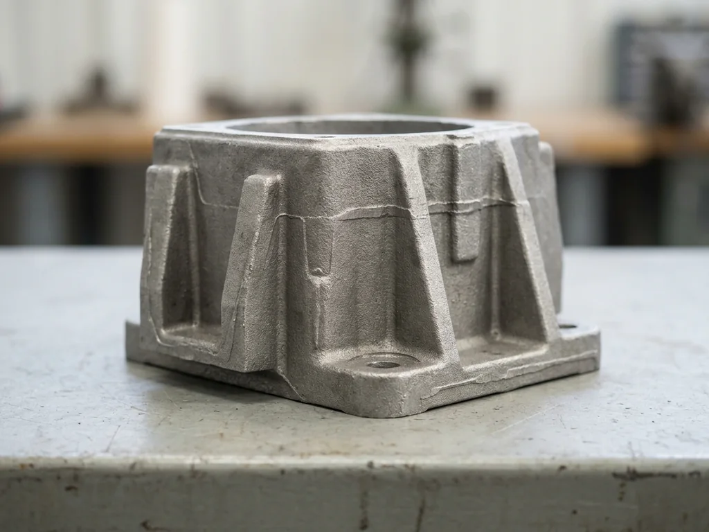
As Cast
As Cast
Some surfaces may remain as-cast after cleaning and trimming if agreed. The drawing must distinguish acceptable gate, ejector and parting-line zones from faces requiring machining or coating.
Anodizing
Anodizing
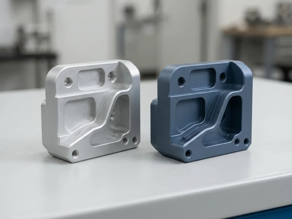
Anodizing is assessed for the selected aluminum alloy and casting condition. Coating requirements, masking and appearance acceptance must be specified, with color and finish agreed for the actual part.
Sand Blasting
Sand Blasting
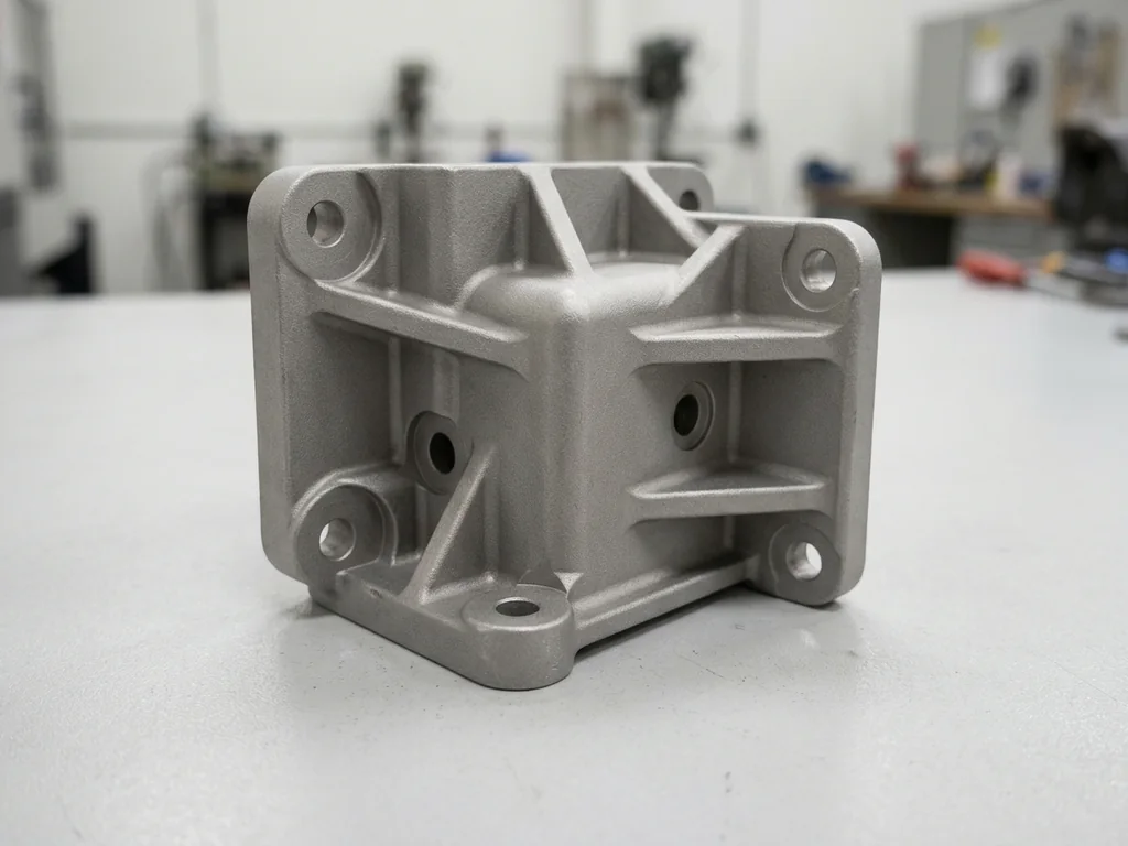
Blasting can remove coating residue and create a matte reference surface. Agree the surface preparation, protected features and acceptance sample for the alloy.

Painting
Painting
The intended environment informs the paint-system, color and gloss requirements. Surface preparation, masking and any coating tests are agreed in the quotation.
Powder Coating
Powder Coating
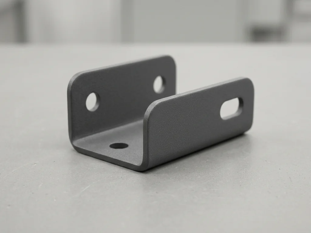
Powder-coating suitability depends on alloy, operating environment and cosmetic requirements. Preparation, masking and acceptance criteria define the work on the coated areas.

Polishing
Polishing
Casting condition and the intended appearance guide polishing review. A reference sample identifies the target, while agreement is needed on which faces can be processed without changing critical geometry.
Sealing faces, bores, threads and mounting datums may require CNC machining after casting. Machining stock and finished-feature tolerances must remain separate from as-cast reference values.





Industry slide guide: 1: Robotics; 2: Automotive; 3: Energy Equipment; 4: Electronics; 5: Industrial Equipment; 6: Other Applications.
Gravity Die Casting for Robotics
Robotics housings, brackets and joints need defined loads and mating datums. Casting geometry and CNC finishing are reviewed against the actual assembly.
View MoreGravity Die Casting for Automotive
Automotive bracket and housing concepts are assessed for load, temperature and inspection requirements. Safety-critical use requires project-specific validation and acceptance.
View MoreGravity Die Casting for Energy Equipment
Motor housings and enclosures bring thermal, sealing and installation requirements into the project review.
View MoreGravity Die Casting for Electronics
Electronics enclosures and heatsinks need coordinated mounting, thermal and cosmetic requirements. The intended use determines the alloy-and-finish review.
View MoreGravity Casting for Industrial Equipment
Define the alloy, load, machined interfaces and inspection for the proposed housing or component.
View MoreGravity Casting: Other Applications
Specify the part function, alloy and condition, dimensional datums and acceptance tests for the project.
View MoreFrequently asked questions
These answers cover drawings, alloys, quantities, tooling schedules and inspection reports for gravity casting. Part-specific requirements can be discussed with the quotation; the Help Center provides another reference point.
What information is needed for a gravity die casting quote?

The quotation requires a 3D model, with a supporting 2D drawing recommended, plus alloy and condition, quantity, critical features, cores, machining, finish and inspection needs. We can sign an NDA upon request before you share design files.
What is the minimum order quantity for gravity die casting?
The company’s general inquiry policy starts at one piece, with typical company orders of 10–1,000 parts. For gravity die casting, the proposed foundry must confirm the feasible minimum batch, trial quantity, die and tooling charges for the actual part. Include first-batch and repeat demand when comparing processes.
Can I approve samples before full production?
Sample approval can be defined in the quotation through the quantity, checks and approval terms. Dimensional, appearance and functional acceptance must be stated before production release; sample charges follow the quotation.
What affects tooling and production lead time?
For 10–100 parts, the company’s usual 3–10 business-day manufacturing reference is considered only after an accepted die, alloy, foundry arrangements and production scope are confirmed. New tooling, trials, sourcing, other quantities and transit need separately agreed schedules. Routine expediting is unavailable.
What inspection documents are available?
Sampling inspection reports are free. Full-inspection and FAI reports are charged. Specify the drawing revision, critical features, required tests and reporting scope when requesting a quote.