


Silicone Compression Molding
Sealing or tactile function determines the review of a solid-silicone compression-molded part. Compound, Shore A hardness and geometry are assessed before tooling, samples and inspection are agreed with LEAD MFG. Thermoset-plastic and fiber-composite projects need separate process assessment.

























Solid Silicone Compression Molding
Solid-silicone compression molding is assessed for a specified compound, tool and acceptance requirements. Required function and operating media guide VMQ/HCR or FVMQ selection; compression geometry and tolerances must be assessed separately from LSR injection.


Assess the design
We can sign an NDA upon request before you share design files. A 3D design file is required; a 2D drawing is recommended to define sealing surfaces, parting line, dimensions and cosmetic faces. Include compound, hardness and quantities.

Compound and hardness
3D model required
Inspection needs

Prepare tooling
The quotation defines the compression tool, cavity and parting approach, overflow grooves, demolding and deflashing requirements. Additional design-for-manufacturing work and its cost must be agreed before authorization.
Parting and overflow
Demolding and flash
Tooling terms
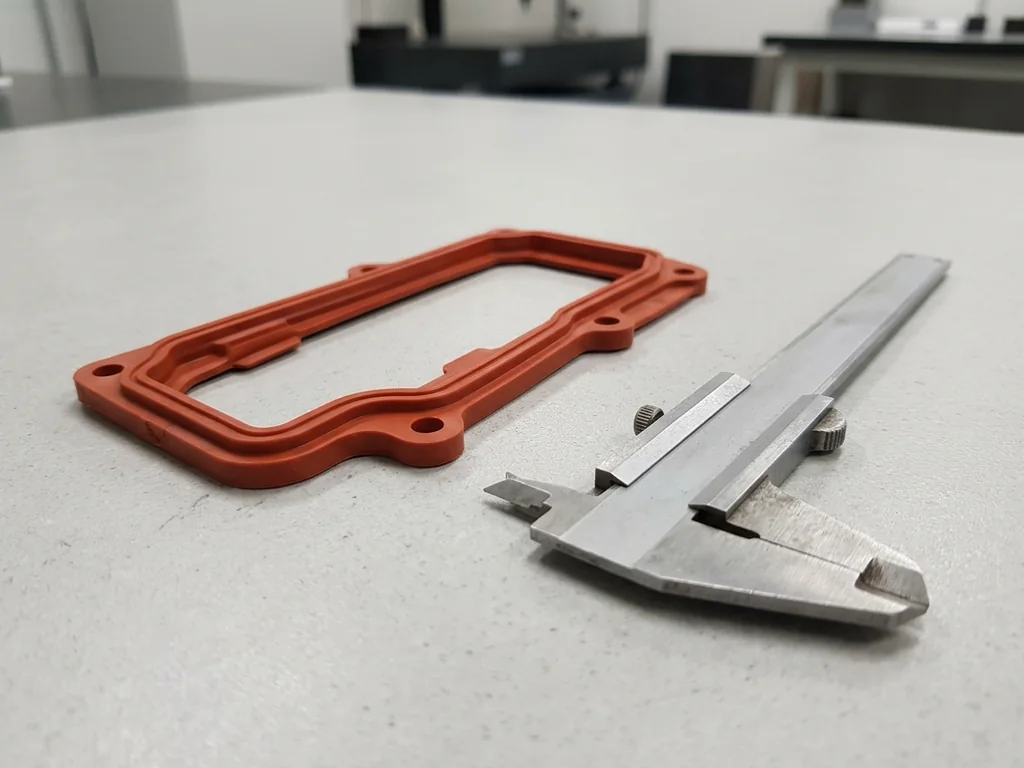
Form and check samples
Evaluate production-tool samples for dimensions, flash, hardness, appearance and mating fit. Sample charges are quotation-specific; sample-price credit applies only to a confirmed volume order.
Production-tool samples
Hardness and fit
Sample acceptance
Solid Silicone Compression Capability References
These values concern solid-silicone compression molding, not liquid silicone injection. The 350 T part-size reference is derived; confirm the compound, tool, geometry and inspection for the actual part. Scroll horizontally for all conditions.
Parameter | Reference | Conditions |
|---|---|---|
Part size / mass | ≤400 × 400 × 50 mm; ≤600 g | ≤400 × 400 × 50 mm; single part ≤600 g. The part-size limit is derived for the 350T compression-molding setup, not an LSR shot specification. Confirm the part geometry and tool suitability for the drawing. |
Dimensional tolerance | Standard ±0.150 mm; conditional best ±0.100 mm | Standard: ±0.150 mm. Conditional best reference: ±0.100 mm with a steel tool and stable shrinkage, subject to specific machine/part confirmation. The 200 mm compression-seal reference remains ±0.150 mm; the best figure is not a blanket tolerance for every size or seal. |
Minimum wall / cord diameter | Wall 0.8 mm; cord Ø1.0 mm | Compression reference: wall 0.8 mm; cord Ø1.0 mm. Wall thickness and cord diameter are separate features; review material, parting, undercuts and demolding for the actual shape. Do not substitute LSR's thinner-feature values. |
Hardness / tolerance | 30A–80A; standard ±5 Shore A | Compression range: 30A–80A. Hardness tolerance: standard ±5 Shore A; conditional best ±3 Shore A requires the same batch and same drum, plus process/part confirmation. The documented range describes hardness selection, not the tolerance on a specified hardness. |
Flash limit | Standard ≤0.100 mm; conditional best ≤0.050 mm | Standard: ≤0.100 mm. Conditional best reference: ≤0.050 mm with precision deflashing. A tighter flash request needs a precision tool and the quoted cryogenic-deflashing process; confirm the flash location, measurement and acceptance requirement. |
Solid Silicone Compound References
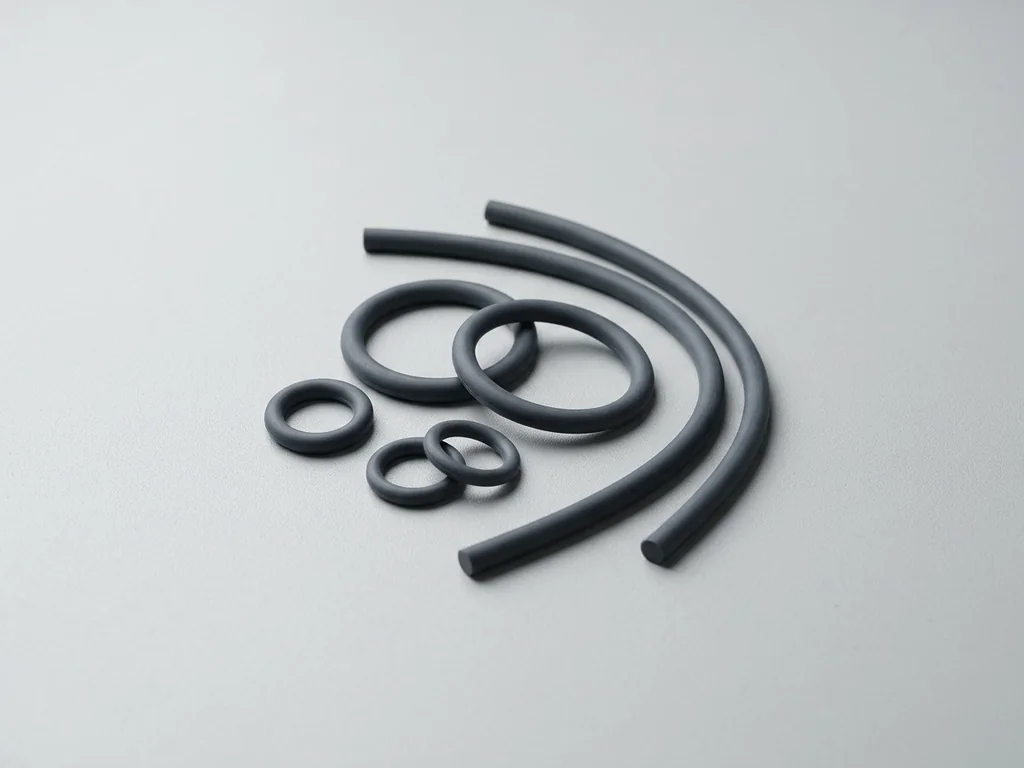
These solid-silicone compound families are starting points for review. Specify the compound, Shore A target, service media and documentation; suitability and supply are confirmed for the project. The compression reference covers 30A–80A; the specified hardness target and its tolerance are separate requirements.

VMQ / High-Consistency Silicone
FVMQ / Fluorosilicone
Silicone Compression Finishing and Secondary Work
Mold surface, flash removal and any secondary work affect the finished silicone part. Define cosmetic and sealing surfaces, the work to be provided and acceptance criteria for the project.

As Molded
As Molded
Identify cosmetic and functional faces, parting lines, tool-surface expectations and the acceptable appearance on the drawing.
Deflashing
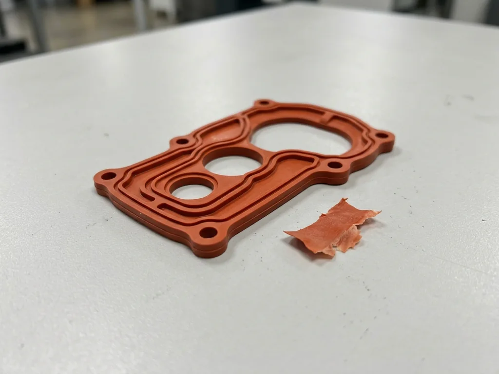
Deflashing
Specify flash location and limit. Review trimming or precision deflashing and the method used to inspect the result.
Cleaning and Protection
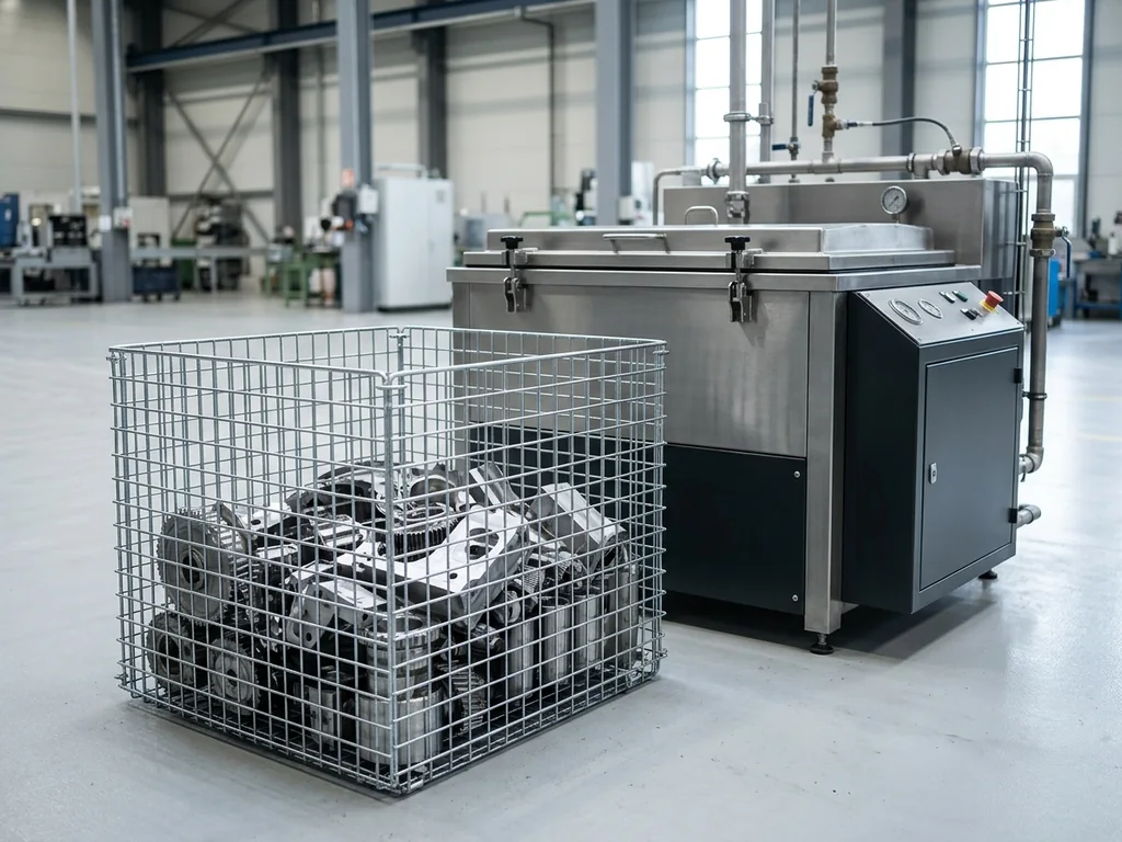
Cleaning and Protection
Define cleanliness, handling and packing requirements for the selected silicone compound and intended use.

Post-Cure
Post-Cure
Where required for the specified compound or application, agree the post-cure process and any effects on dimensions and acceptance.
Bonding or Marking
Bonding or Marking
If the part requires bonding or marking, specify interfaces, artwork and acceptance tests; confirm material compatibility and the work to be provided.





Industry slide guide: 1: Aerospace; 2: Automotive; 3: Automation; 4: Medical Devices; 5: Robotics; 6: Consumer Products.
Silicone Compression Molding for Aerospace
For a proposed silicone part, define compound, hardness, service environment and the applicable qualification requirements.
View MoreSilicone Compression Molding for Automotive
For seals or protective parts, identify compound, compression behavior, operating media and the required tests.
View MoreSilicone Compression Molding for Automation
For pads or isolation components, define material hardness, fit, loading and operating conditions.
View MoreSilicone Compression Molding for Medical Devices
For an equipment component, specify compound, cleanliness, documentation and intended use; qualification requires separate review.
View MoreSilicone Compression Molding for Robotics
For tactile or protective interfaces, identify hardness, geometry, operating conditions and inspection requirements.
View MoreSilicone Compression Molding for Consumer Products
For buttons and pads, define visible surfaces, color, hardness, feel and the sample acceptance criteria.
View More

Frequently asked questions
These answers cover solid-silicone compounds, tooling, appearance, secondary work, inspection and schedules. Confirm the drawing and quotation requirements before production.
Which silicone compounds can be reviewed?

The service covers solid-silicone compression molding, including discussion of VMQ/HCR or FVMQ for the required Shore A hardness, color, temperature and operating media. Thermoset plastics, reinforced composites and other elastomers need their own material/process assessment. Medical or food-contact evidence must be specified for the selected compound and use.
Is compression molding suitable for prototypes?
Prototype feasibility is assessed through trial quantity, likely design changes, tooling and sample checks before a build is authorized. The general order policy starts at one part, with typical orders of 10–1,000 parts; feasibility, sample price and tool requirements remain quotation-specific.
What should be considered when planning a compression mold?
Part geometry, parting lines, undercuts, overflow, demolding and flash limits all affect the tool. Identify functional and cosmetic faces so the tooling and sample checks can be agreed before release.
How are inspection reports agreed?
Sample inspection reports are free. Full inspection and first article inspection (FAI) reports are charged. Define the sampling plan, critical checks and required records in the quotation before production.
How are tooling and production schedules agreed?
For 10–100 parts, the usual company manufacturing reference is 3–10 working days from quotation confirmation when the mold has been completed and accepted and the compound and production plan are confirmed. New tooling and other quantities require a separate project schedule. Expedited production is not normally available; urgent exceptions require discussion, and the quotation establishes the agreed timing.