


Custom Injection Molding
Resin, part geometry and quantity shape an injection-molding project. A quotation for molded prototypes or production parts brings these choices together with tooling, critical dimensions, appearance and inspection requirements.













Injection Molding Services and Capabilities
Part design, resin and production purpose connect the molding plan to the tool. Insert molding and overmolding also depend on defined materials, interfaces and acceptance criteria; the project agreement needs to cover those requirements.


Injection Molding
Injection molding is an option when the part design and resin are suitable for the process. Tooling and production planning depend on the exact grade, geometry, quantity, finish and inspection requirements for the order.

Resin and part geometry
Tooling review
Inspection plan
Injection Mold Tooling
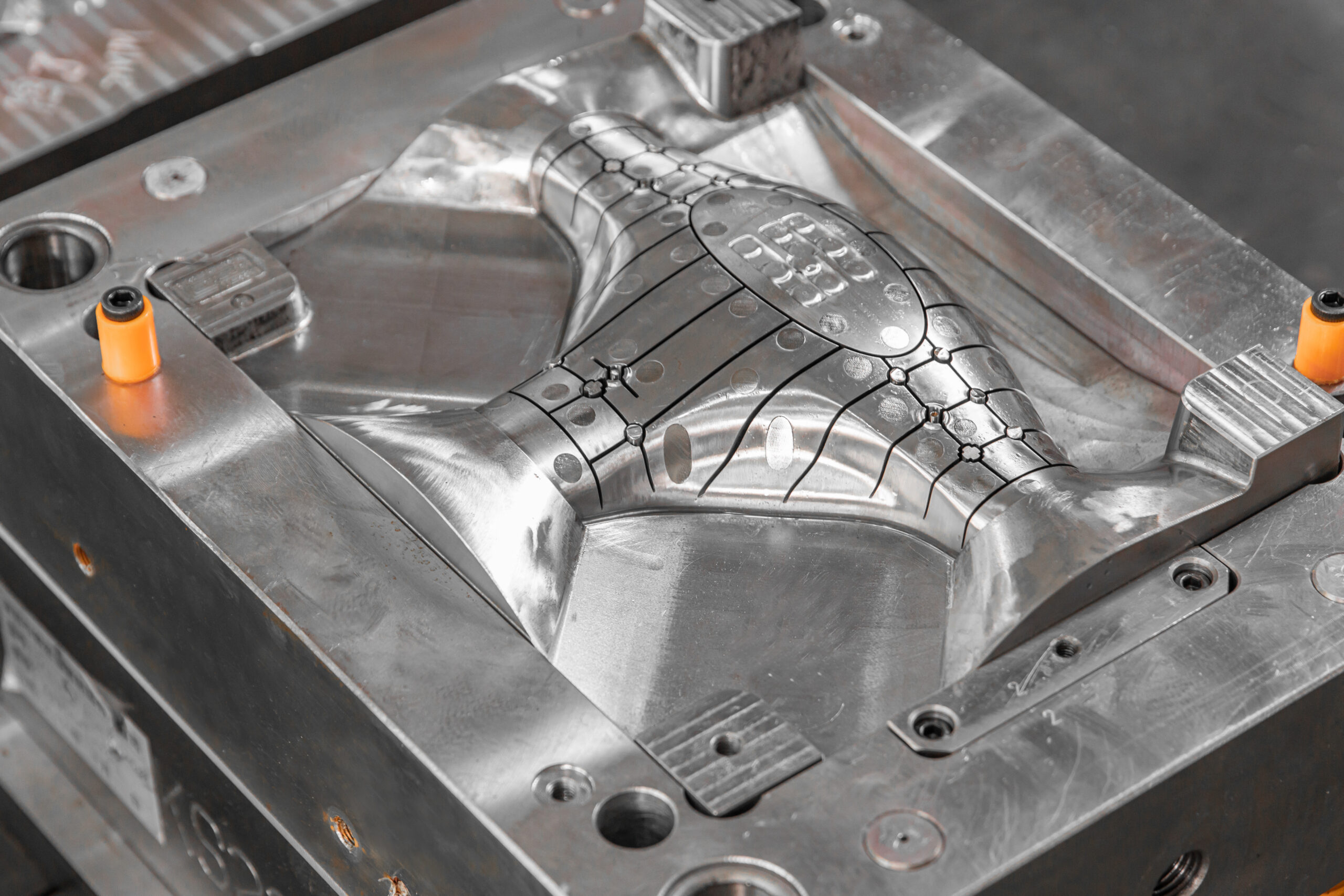
Tool material, cavity layout and expected use affect how the tool and trial parts are specified. The quotation needs project-specific terms for tool life, maintenance, storage, ownership and any analysis work.
Tool material
Cavity layout
Trial requirements

Insert Molding & Overmolding
Insert molding places a defined insert in the mold before forming the surrounding body. Specify the insert material, shape, location, exposed surfaces and retention requirements so the resin, tool and inspection approach can be assessed. For an overmolding request, identify the substrate, overmold material, interface, surface preparation and required bond or mechanical retention. Assess the proposed material pair and tooling approach separately; this is not a promise of universal adhesion or general two-shot molding.
Insert and substrate
Interface and retention
Material compatibility
Injection Molding Capabilities
We provide in-house horizontal injection molding with 120–300 T presses, and separately offer 40 T vertical insert molding. At 300 T, the reference part-size limit is ≤350 × 350 × 180 mm and shot capacity is ≤420 g PS equivalent. Resin, total projected area, cavity pressure, tooling and inspection requirements determine the quoted part capability. Scroll horizontally on narrower screens to read all conditions.
Parameter | Capability | Conditions |
|---|---|---|
Clamping force | 120–300 T; 120 / 160 / 260 / 300 T tiers | For horizontal molding, total projected area, cavity pressure and shot demand determine the press tier. Horizontal projects outside the 120–300 T range require a separate manufacturing assessment. The 40 T vertical insert presses are listed separately below. |
Maximum part size | 300 T: ≤350 × 350 × 180 mm; 160 T: ≤250 × 250 × 120 mm | Reference part dimensions. Mold fit, projected area, shot capacity and ejection clearance must also be checked. |
Shot weight | Minimum 0.1 g; maximum ≤420 g PS equivalent | PS-equivalent shot reference; assess the selected resin and combined cavity filling requirement. |
Projected area | Approx. 750 cm² at 300 T | Derived at 40 MPa cavity pressure; recheck total projected area against actual cavity pressure and clamping requirement. |
Part-to-part repeatability | ±0.100 mm | Standard part-to-part reference for the agreed resin, mold and process; this is not mold-cavity machining accuracy. |
Critical dimension tolerance | ±0.050 mm | After shrinkage compensation and gauging, with shrinkage stabilized; identify the critical dimensions and inspection method. |
Mold-cavity tolerance | Class 105: ±0.020 mm; Class 104: ±0.015 mm | Tool-cavity values by class. Molded-part tolerances remain separate because resin shrinkage varies through the part. |
Wall thickness | 0.5–4.0 mm; typical 1.2–2.5 mm | ABS / PC: ≥1.2 mm. Resin flow, geometry and uniform sections determine the usable wall. |
Wall transitions | Thickness step ≤25% | Relative to the adjoining wall; review gradual transitions for filling, sink and differential shrinkage. |
Minimum features | Part: 5 × 5 × 2 mm; core: Ø0.8 mm | Minimum reference features; verify resin filling, core strength, tooling and ejection for the geometry. |
Draft angle | Polished: 0.5–1.5°; textured: 1.5–2.5° | Add 1° for each 0.025 mm of texture depth; model the draft and check demolding direction. |
Ribs | Thickness: 0.5–0.6 × wall; height: ≤3 × wall | Based on adjacent wall thickness; check filling and sink risk at cosmetic surfaces. |
Bosses | Outside diameter = 2 × inside diameter; root fillet R0.5 | Drawing units, the root fillet and mating hardware define the interface. Assembly loads and ejection requirements also need assessment. |
Cavity layout | Single cavity standard; multi-cavity usually ≤4 | Multi-cavity selection requires clamping and total shot checks; part-family layout and balance must be assessed. |
Vertical insert molding | 40 T: ≤200 × 150 × 100 mm | In-house 40 T vertical insert presses. For brass, stainless-steel or stamped-copper inserts; confirm resin compatibility, insert position and retention with the tool. |
Mold classes | Class 105 prototype; Class 104 bridge | Validation and bridge production are the intended uses. A Class 105 trial tool does not provide a production cosmetic reference. |
Mold surface finish | SPI A-1–D-3; Class 104 reference: B-2–C-1 | A-1 requires hardened S136; confirm resin, filler, texture and cosmetic acceptance. |
Warpage / flash | Warpage: ≤0.2 mm / 100 mm; flash: ≤0.05 mm | Measurement span, parting-line and flash zones define the inspection requirement. The agreed part criteria must also be supported by the resin, filling and cooling conditions. |
Injection Molding Materials
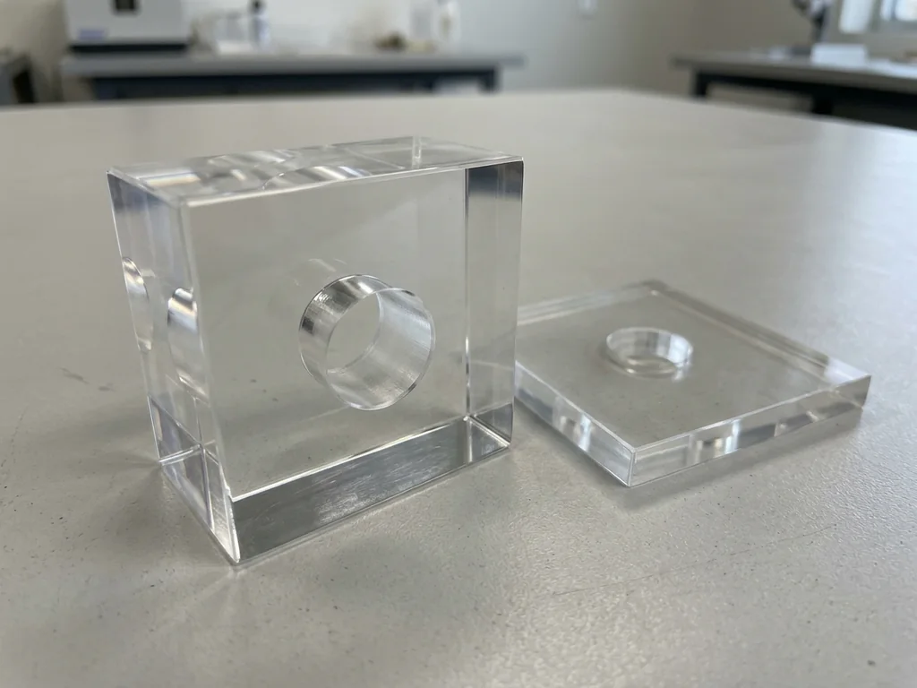
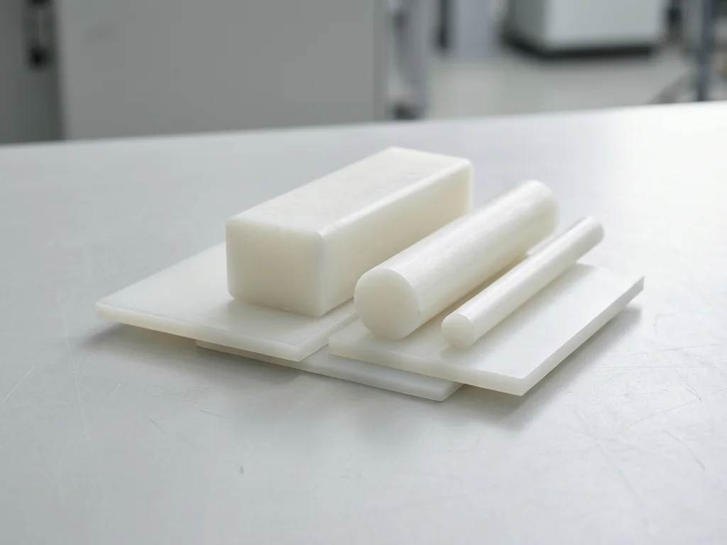
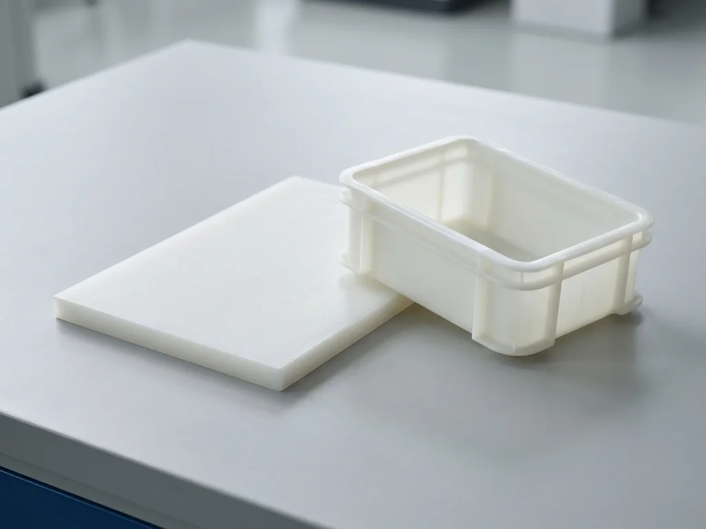
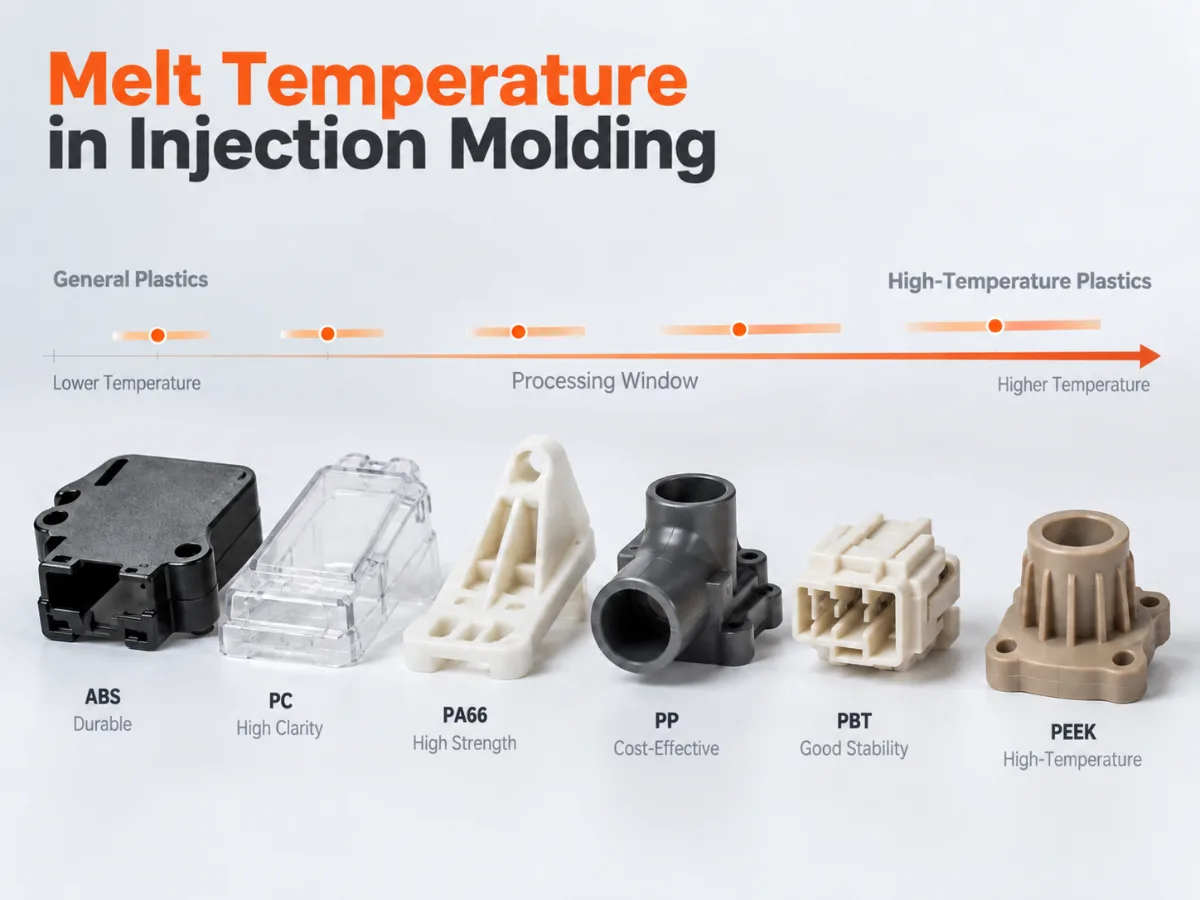
Resin-family names help organize a material request, but they are not a current-stock list. Selection depends on the exact molding grade, additives, color, service conditions and required documents. Availability and suitability require assessment for the part. PTFE and UPE need separate process review and are not standard injection-molding materials on this page.

ABS

PC
PMMA (Acrylic)

POM

PA (Nylon)
PE

PEEK
PP
Other materials for process review: HDPE, HIPS, LDPE, PBT, PET, PPS, PS and PVC. PTFE and UPE require a separate process review. Specify the grade, additives, color and applicable requirements for the quotation.
Injection Mold Surface Finishes
SPI finish names are references for discussing the mold surface. Molded appearance also depends on resin, fillers, geometry, demolding and processing. Agree the category, cosmetic surfaces and acceptance criteria for the part; images are examples, not a guaranteed supplier sample.

SPI A
SPI A
A diamond-polished mold surface can be discussed when a gloss reference is required. The proposed resin, cosmetic faces and acceptance sample or measurement method determine the target; a grade name does not guarantee gloss on every molded part. Grades: SPI A1, A2, A3.
SPI B
SPI B
Paper-finished mold surfaces are a separate appearance reference from diamond polish. Specify the visual target and acceptable marks, then assess resin, filler and processing effects with the tooling plan. Grades: SPI B1, B2, B3.

SPI C
SPI C
The stone-finish category provides a matte reference, not a universal finish guarantee. The visual target, cosmetic faces and acceptance criteria still need agreement for the proposed resin and geometry. Grades: SPI C1, C2, C3.

SPI D
SPI D
A dry-blasted surface provides a texture reference to discuss, not a substitute for a defined appearance requirement. Assess texture, demolding, resin and fillers together and agree the acceptance method for the part. Grades: SPI D1, D2, D3.





Industry slide guide: 1: Aerospace; 2: Automotive; 3: Automation; 4: Electronics; 5: Robotics; 6: Consumer Products.
Injection Molding for Aerospace
For molded housings and fittings, define the resin, critical features and documentation needed for project review.
View MoreInjection Molding for Automotive
For molded covers, clips and connectors, specify the material, mating features, appearance and inspection requirements.
View MoreInjection Molding for Automation
For equipment housings and interfaces, share load, operating conditions and assembly requirements for assessment.
View MoreInjection Molding for Electronics
For electronic housings and connectors, identify insulating requirements, interfaces, resin and acceptance criteria.
View MoreInjection Molding for Robotics
For molded covers and mounting components, identify mating geometry, material and operating conditions.
View MoreInjection Molding for Consumer Products
For housings, handles and closures, specify appearance, touch surfaces, fit and intended use.
View More
Frequently asked questions
The answers below cover drawings, resin, tooling, schedules and inspection reports. Questions that affect the part need resolution before ordering.
How much does custom injection molding cost?

Cost depends on part geometry, resin grade, mold requirements and work to be provided, cavity count, quantity, finishing and inspection requirements. Use the current design revision to agree tooling terms, engineering work to be provided, report fees, price and schedule in a project-specific quotation.
How are quotation and trial schedules agreed?
Drawing review, resin availability, tooling preparation and agreed trial requirements shape the schedule. We provide DFM feedback and a project quotation; confirm tool and trial milestones as part of the agreed work. Manufacturing time and transit time are separate. For 10–100 parts, typical production takes 3–10 business days from quotation confirmation when suitable tooling is already accepted and the resin and process are confirmed. New in-house Class 105 and Class 104 tools have reference times to first trial of 7–10 days and 10–14 days respectively. Tooling, trial acceptance, production and transit are separate milestones to agree in the quotation. Other quantities require a project-specific schedule. Expediting is normally unavailable; urgent exceptions require confirmation.
Is there a minimum order quantity?
Orders start at 1 part, with typical quantities of 10–1,000 parts. Sample pricing is quotation-specific; sample charges can be credited against a confirmed volume production order. Quantity changes may require a new quotation and production schedule.
What tolerance and part-size references apply?
Part-to-part repeatability is ±0.100 mm. Mold-cavity tolerances are ±0.020 mm for Class 105 and ±0.015 mm for Class 104 tools; cavity accuracy and molded-part tolerances are separate measurements. The ±0.050 mm critical-dimension reference requires shrinkage compensation, stabilized shrinkage and gauging. Reference part dimensions are ≤350 × 350 × 180 mm at 300 T and ≤250 × 250 × 120 mm at 160 T; shot capacity is ≤420 g PS equivalent. Actual resin, geometry, total projected area, cavity pressure, mold and press setup, shrinkage and inspection must be agreed for the quoted part.
How are molded parts inspected?
Final inspection follows the agreed sampling plan, critical dimensions, appearance checks and reporting requirements. CMM, optical or other measurement methods must fit the part and ordered inspection scope. Material-property testing requires a separate agreement. Critical features and reporting needs determine the agreed inspection coverage. Sampling inspection reports are free; full inspection and FAI reports are charged. The quotation records the inspection and report requirements.